
TB 1-1500-351-20-1
2.
Cut three (3) pieces of white sleeve marker material into 2" lengths for each cable assembly to be fabri-
cated. If no wire-marking machine is available for marking the white sleeve marker use a black indelible
ink pen and print the cable number on the sleeve marker. Mark the sleeve marker with the information
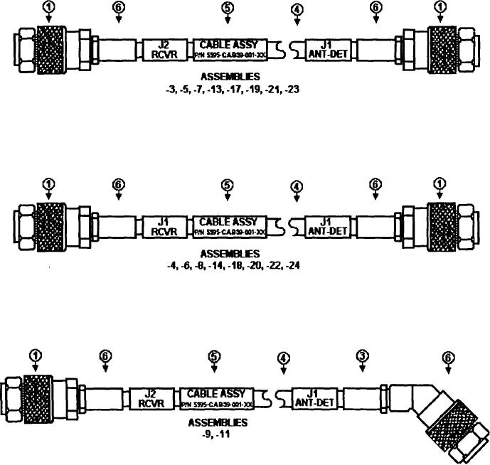
located at the top of the appropriate column for the cable to be fabricated. Example: CABLE ASSY.
5595-CAB39-001-13. Slide the sleeve marker onto the center of the cable assembly and shrink in
place.
3.
Mark the remaining two (2) sleeve markers with the following information. If the cable being fabricated
is for the FWD LEFT mark one of the white sleeve markers with J2 RCVR and the other white sleeve
marker with J1 ANT-DET using a black plastic tip indelible ink pen. Slide the sleeve marker onto each
end of the cable assembly but do not shrink in place until the connectors are installed.
4.
Use the following examples in the fabrication of the cable assemblies that associate to the last two
digits of the New Part Number located in the aircraft charts above.
6

