
TB 1-1520-238-30-19
Figure 14. Use of Spanner Wrench
10.20 Using modified punch (P/N 3210685-3, Figure 15) stake nut (16) into output adapter shaft (19) in two
places, 180 degrees apart.
CAUTION
Ensure splined output adapter (19) threads are not damaged during
crimping operation. Rotate assembly to check for binding.
INSPECTION POINT: VERIFY TORQUE OF 550 INCH POUNDS TO NUT
(16) AND VERIFY NUT IS CRIMPED IN TWO LOCATIONS 180 DE-
GREES APART.
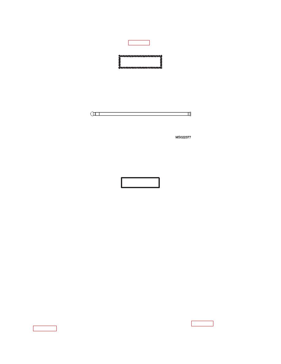
Figure 15. P/N 3210865-3 Modified Punch
10.21 Using isopropyl alcohol, clean mating surfaces of output housing (26) and input housing (12).
10.22 Regrease roller bearing (20).
WARNING
All precautions must be taken to insure that the roller bearing (20) is
not contaminated. If any contamination is suspected reject the
clutch.
10.22.1 A grease quantity not to exceed 1 gram of Mobilgrease28 grease shall be added to the roller bearing
and cavity forward of the roller bearing as follows:
10.22.2 Weigh a grease filled syringe. Record weight as W=______ grams.
10.22.3 Inject Mobilgrease28 grease into the roller bearing cavity (20) from the aft output shaft end, working
the grease over the bearing rollers with the syringe tip or end of a small plastic spatula. Use caution to avoid
getting grease aft of the roller bearing seal (20) packing.
10.23 Output Section Assembly Apply a thin, even coat of Hylomar compound to mating surfaces of outlet
housing (26) and inlet housing assembly (12). Allow Hylomar to cure for a minimum of five minutes to a
maximum of twenty minutes. If housing are not joined within 5 to 20 minutes of applying the Hylomar, remove
all Hylomar from both flanges and repeat process step.
10.24 Remove plastic caps (P/N VC-1000-16, VC-437-16, and VC-812-16) prior to assembly operations
cover open bores with a clean, lint free cloth to prevent contamination if assembly action is delayed.
10.25 Locate missing tooth on clutch friction disk on input housing assembly (12) and align with smallest
diameter hole (o.44 inch) in splined output adapter (19). Alignment can be viewed through inspection hole.
The inspection hole must be lined up with solenoid valve at the clutch 12 o'clock position. The data plate would
be at the 12 o'clock position.
INSPECTION POINT: VERIFY MISSING TOOTH ON CLUTCH FRIC-
TION DISK IS ALIGNED WITH SMALLEST DIAMETER HOLE IN
SPLINED OUTPUT ADAPTER (19).
10.26 Install assembled output housing (26) onto input housing (12). If a tooth is present when viewing
through the output housing inspection hole the assembly is incorrect. Repeat para 10.25 and resume with
23

