TM 1-1520-238-23
4-111
4.35.
ENGINE BUILDUP – NO. 1 AND NO. 2 ENGINE DRAIN SYSTEM INSTALLATION (T700-GE-701C
ENGINE) – continued
e. Install drain manifold (15) on union (8). Torque
nut (16) to 290 INCH-POUNDS.
(1) Lubricate threaded area of union (8). Use
petrolatum (item 138, App F).
(2) Hold union (8). Install nut (16).
(3) Torque nut (16) to 290 INCH-POUNDS. Use
torque wrench and crowfoot.
f. Install swirl frame drain line (17) on manifold
(15) and union (4). Torque nuts (18) and (19) to
120 INCH-POUNDS.
(1) Lubricate threaded area of manifold (15) and
union (4). Use petrolatum (item 138, App F).
(2) Install line (17) on union (4).
(3) Hold union (4). Install washer (20) and nut
(18).
(4) Hold manifold (15). Install nut (19).
(5) Torque nuts (18) and (19) to 120 INCH-
POUNDS. Use torque wrench.
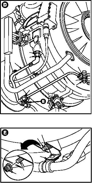
g. Install common drain line support clip (21) on
main frame mounting stud (22). Torque nut (23)
to 22 INCH-POUNDS.
(1) Remove nut (23) from stud (22).
(2) Position clip (21) on stud (22).
(3) Reinstall nut (23) on stud (22).
(4) Torque nut (23) to 22 INCH-POUNDS. Use
torque wrench.
GO TO NEXT PAGE
19
15
M04-3700-6
4
20
17
16
8
18
M04-3700-7
22
23
23
22
21