TM 1-1520-238-23
4-550
4.164.
NO. 1 OR NO. 2 POWER AVAILABLE SPINDLE CABLE CONNECTING LINKS
REMOVAL/INSTALLATION
4.164.1. Description
This task covers:
Removal. Cleaning. Inspection. Installation
4.164.2. Initial Setup
Tools:
Aircraft mechanic’s tool kit (item 376, App H)
0 - 30 inch-pound 1/4-inch drive dial indicator torque
wrench (item 445, App H)
Materials/Parts:
Cotter pin (4)
Personnel Required:
67R
Attack Helicopter Repairer
67R3F
Attack Helicopter Repairer/Technical
Inspector
Equipment Conditions:
Ref
Condition
1.57
Helicopter safed
2.2
Console panels PL1 and PL3 removed
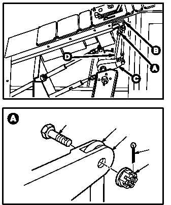
4.164.3. Removal
a. Remove rod end (1) from No. 1 power lever (2).
(1) Position power lever (2) in LOCKOUT posi-
tion.
(2) Remove and discard cotter pin (3).
(3) Hold bolt (4). Remove nut (5).
(4) Remove bolt (4) from power lever (2) and rod
end (1).
GO TO NEXT PAGE
M04-3929-1
2
1
4
5
3
M04-3929-2