TM 1-1520-238-23
Change 6
4-667
4.184.
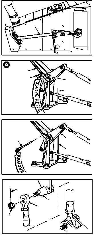
NO. 1 OR NO. 2 ENGINE LOAD DEMAND SPINDLE RIGGING CHECK – continued
b. Move pilot collective stick (1) through full up
and full down positions.
c. Move pilot collective stick (1) to full down
position.
d. Install –7 rig pin (2) in upper rig pin hole (3) of
bracket (4) and bellcrank (5).
(1) If rig pin cannot be installed, system is out of
rig (para 4.185).
e. Remove –7 rig pin (2) from bracket (4) and
bellcrank (5).
f. Remove external power – electrical (para
1.70).
g. Remove external power – hydraulic (primary)
(para 1.72).
h. Remove rod end (6) from collective servoac-
tuator adapter (7).
(1) Remove and discard cotter pin (8).
(2) Hold adapter (7) by flats, remove nut (10).
(3) Remove rod end (6) from adapter (7).
GO TO NEXT PAGE
PILOT STATION
M04-1209-7
1
4
M04-1209-8
5
2
3
5
4
M04-1209-6
2
RIG PIN
6
7
M04-1209-15
8
9