TM 1-1520-238-23
4-708
4.192.
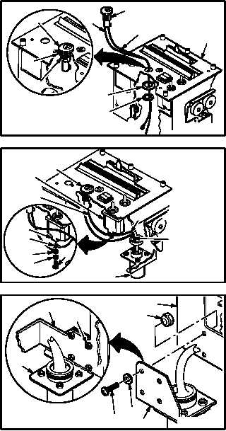
PILOT POWER QUADRANT PANEL – IGNITION LOCK SWITCH REMOVAL/INSTALLATION
(AVIM) – continued
4.192.6. Installation
a. Install MASTER IGN switch (15) on panel (2).
(1) Guide wires (6) and (8) through panel (2) and
seat switch (15) in panel (2).
(2) Install lockwasher (17) and nut (16). Use
crowfoot.
b. Pin
wire
(6)
in
connector
J1
(7)
(TM 55-1500-323-24).
c. Attach wires (8) and (9) on ENG NO. 1 IGN
OVRD switch (10).
(1) Install screw (11) through washer (12), termi-
nal lugs (13) and (14), into terminal 2 (18) of
switch (10).
d. Install lacing tape as required. Use tape
(item 202, App F).
e. Install bracket (1) on panel (2).
(1) Install four screws (3), through washers (4),
bracket (1), and panel (2) into locknuts (5).
f. Inspect (QA).
g. Install pilot power quadrant power levers
(para 4.167).
END OF TASK
M04-3332-6
15
17
15
8
17
16
6
2
16
18
14
13
12
11
M04-3332-7
6
7
9
15
10
8
4
3
2
5
1
2
5
M04-3332-9
1
VIEW ROTATED