TM 1-1520-238-23
8-117
8.45.
DUAL HYDRAULIC PRESSURE INDICATOR REMOVAL/INSTALLATION – continued
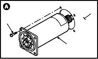
c. Remove dual hydraulic pressure indicator (1)
from instrument panel (2).
(1) Remove four screws (3).
(2) Pull indicator (1) from panel (2).
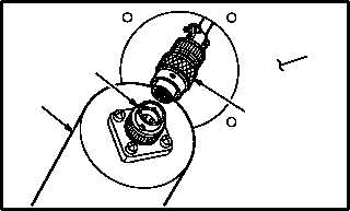
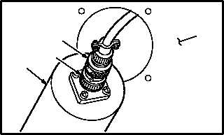
(3) Detach connector P265 (4) from receptacle
(M28)J1 (5).
8.45.4. Cleaning
a. Wipe mounting area and indicator with a clean
rag.
8.45.5. Inspection
a. Check indicator and panel mounting area for
cracks, nicks, and dents (para 8.43).
b. Check panel screw holes for stripped or dam-
aged threads (para 8.43).
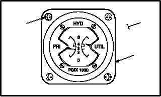
8.45.6. Installation
a. Install indicator (1) in panel (2).
(1) Attach connector P265 (4) to receptacle
(M28)J1 (5).
(2) Aline indicator (1) with screw holes in panel
(2).
(3) Install four screws (3).
b. Inspect (QA).
c. Perform primary or utility hydraulic mainte-
nance operational check (TM 1-1520-238-T).
END OF TASK
M04-191-3
3
1
2
M04-191-4
1
5
4
2
M04-191-5
1
4
2
5
2
1
3
M04-191-6