TM 1-1520-238-23
Change 3
11-1151
11.272. DIRECTIONAL F.S. 542 BELLCRANK REMOVAL/INSTALLATION – continued
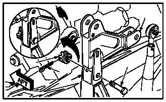
11.272.6. Installation
CAUTION
To prevent damage to flight control sys-
tem components, do not use force to
aline bellcrank with bracket or to aline
push-pull rod with bellcrank.
a. Install bellcrank (4) on bracket (14). Torque nut
(13) 30 to 40 INCH-POUNDS.
(1) Aline bellcrank (4) with bracket (14).
(2) Install bolt (12) through bracket (14) and bell-
crank (4).
(3) Check fit of self-retaining bolt (12) (para
11.1).
(4) Install nut (13). Torque nut (13) to 30 INCH-
POUNDS. Use torque wrench.
(5) Increase torque to aline cotter pin hole, but do
not exceed 40 INCH-POUNDS.
(6) Install cotter pin (15).
NOTE
Do not apply sealing compound to spheri-
cal bearing.
(7) Apply sealing compound to head of bolt (12)
and nut (13). Use sealing compound
(item 178, App F).
GO TO NEXT PAGE
M04-1772-5A
4
14
15
13
12