TM 1-1520-238-10
3-71
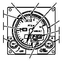
3.18 ALTIMETER AN/APN-209(V).
The radar altimeter system (fig 3-27) provides instanta-
neous indication of actual terrain clearance height. Alti-
tude, in feet, is displayed on a radar altimeter indicator on
the instrument panel in front of the pilot. The radar altime-
ter indicator contains a pointer that indicates altitude on a
linear scale from 0 to 200 feet (10 feet per unit) and on a
second-linear scale from 200 to 1500 feet (100 feet per
unit). An on/OFF/LO altitude bug set knob, on the lower
left corner of the indicator, combines functions to serve as
low level warning bug set control and on/OFF power
switch. The system is turned on by turning the LO control
knob, marked SET, clockwise from OFF. Continued clock-
wise turning of the control knob will permit the pilot to se-
lect any desired low-altitude limit as indicated by the LO
altitude bug. Whenever the altitude pointer exceeds low-
altitude set limit, the LO altitude warning light will go on.
Turning the PUSH-TO-TEST HI SET control on the lower
right corner of the indicator positions the high altitude bug.
Whenever the pointer exceeds the HI altitude set limit, the
high altitude warning light will come on. Pressing the
PUSH-TO-TEST HI SET control provides a testing feature
of the system at any time and altitude. When the PUSH-
TO-TEST HI SET control knob is pressed, a reading be-
tween 900 feet and 1100 feet on the indicator, and digital
display will be displayed. The OFF flag removed from view
indicates satisfactory system operation. Releasing the
PUSH-TO-TEST HI SET control knob restores the system
to normal operation. Loss of system power will be indi-
cated by the indicator pointer moving behind the dial mask
and the OFF flag reappearing in the center of the instru-
ment. If the system should become unreliable, the flag will
appear and the indicator point will go behind the dial mask
to prevent the pilot from obtaining erroneous readings.
Flight operations above 1500 feet do not require that the
system be turned off. The pointer will go behind the dial
mask but the transmitter will be operating. Power to oper-
ate the AN/APN-209 is supplied from the emergency dc
bus through the RDR ALT circuit breaker on the pilot cen-
ter circuit breaker panel.
3.18.1 Antenna.
The radar altimeter antenna (fig 3-1)
are flush-mounted in a fairing on the bottom of the helicop-
ter. The aft antenna is the transmitting antenna and the
forward is the receiving antenna.
3.18.2 Controls, Indicators, and Functions.
Control
of the radar altimeter set is provided by the LO SET OFF
knob on the front of the height indicator. The knob marked
HI SET also controls the PUSH TO TEST. Control and in-
dicator functions of the AN/APN-209 altimeter set are de-
scribed in table 3-24.
HI WARNING
LIGHT
HI SET BUG
(INDEX)
ALTITUDE
POINTER
LO SET BUG
(INDEX)
LO WARNING
LIGHT
LO SET
KNOB
DIAL MASK
DIGITAL
READOUT
HI SET
KNOB
SYSTEM OFF FLAG
(OUT OF VIEW BEHIND DIAL MASK)
M01-037
Figure 3-27.
Altimeter AN/APN-209(V)