TM 1-1520-238-23
4-30
4.9.
NO. 2 ENGINE REMOVAL – UPPER DISCONNECTION – continued
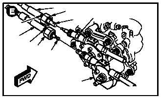
g. Remove load demand cable assembly (26)
from load demand spindle gearbox (27).
(1) Hold cable housing flats (28). Remove cou-
pling nut (29).
(2) Pull cable (30) inboard and remove.
h. Remove power available cable assembly (31)
from power available spindle gearbox (32).
(1) Hold cable housing flats (33). Remove cou-
pling nut (34).
(2) Pull cable (35) inboard and disconnect.
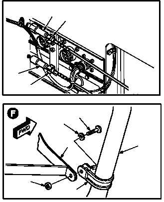
i. Stow power available cable (31) in upper clip
(36).
j. Stow load demand cable (26) in lower clip (37).
k. Remove starter air tube (38) from support (39).
(1) Hold screw (40). Remove nut (41).
(2) Remove screw (40) and washer (42) from
clamp (43).
GO TO NEXT PAGE
33
26
2829
30
27
35
34
31
32
M04-1005-7
31
36
26
37
M04-1005-8
M04-1005-9
39
42
40
38
43
41