TM 1-1520-238-23
Change 4
5-193
5.43.
MAIN ROTOR HEAD ASSEMBLY (AVIM) – continued
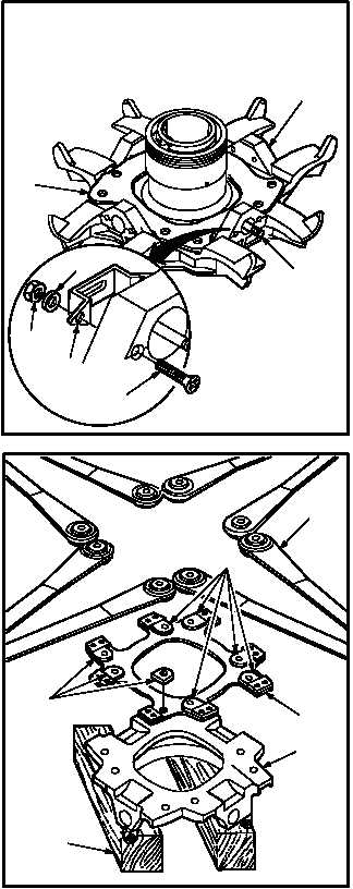
i. Install four brackets (6) on hub (2). Torque
eight nuts (9) to 20 INCH-POUNDS.
(1) Aline four brackets (6) with hub (2) mounting
holes and key of four studs (3).
(2) Install eight screws (7) through hub (2) and
brackets (6).
(3) Install eight washers (8) and nuts (9) on
screws (7).
(4) Hold eight screws (7). Torque eight nuts (9) to
20 INCH-POUNDS. Use torque wrench.
NOTE
Hub, hub load plate, hub plate, and lower
shoe each have a small index bump on
outer edge contour. Index bumps are pro-
vided for alignment of bolt holes in hub.
Alignment with index bumps are recom-
mended but not mandatory.
j. Assemble lower shoe (10), hub plate (11),
spacers (12), and four strap packs (13).
(1) Place shoe (10) on wood blocks.
(2) Place hub plate (11) on shoe (10) and aline
bolt holes.
(3) Place two spacers (12) on hub plate (11) at
each bolt hole.
(4) Place strap packs (13) on spacers (12) and
aline bolt holes.
GO TO NEXT PAGE
M04-247-2
1
2
9
6
7
8
3
13
11
10
12
12
BLOCKS
M04-247-1