TM 1-1520-238-23
5-221
5.48.
MAIN ROTOR ELECTRICAL BRUSH, ELECTRICAL HOLDER, AND PITCH WEB ELECTRICAL
LEAD REMOVAL/INSTALLATION – continued
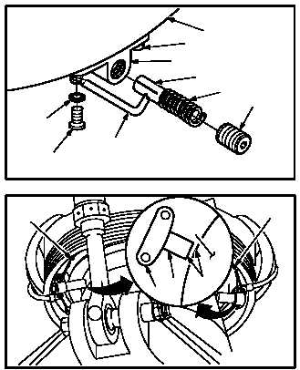
e. Install holder (3) and lead (5).
(1) Position holder (3) on retainer (9).
(2) Install second bolt (6) through washer (8),
lead (5), holder (3), and in retainer (9).
(3) Lockwire two bolts (6) to capscrews (7). Use
wire (item 225, App F).
(4) Apply sealant to bolt (6) and lead (5) mount-
ing area. Use sealing compound (item 175,
App F).
NOTE
If installing a used static brush, ensure
radius of brush tip alines with radius of
mast edge. Misalinement will cause ex-
cessive static in the communication sys-
tem.
f. Install brush (1).
(1) Install brush (1) and spring (4) in holder (3).
(2) Install setscrew (2) in holder (3).
(3) Tighten setscrew (2) until outer edge of set-
screw (2) is flush with holder (3).
g. Perform electrical bond check on electrical
leads (TM 55-1500-323-24).
(1) Bond shall be 1.00 OHM or less. Use
multimeter.
h. Inspect (QA).
END OF TASK
M04-216-4
9
3
2
4
1
6
8
5
6
M04-216-5
1
7
7
RADIUS
3
MAIN
ROTOR
MAST