TM 1-1520-238-23
4-227
4.70.
NO. 1 OR NO. 2 ENGINE ANTI-ICE TUBE REMOVAL/INSTALLATION
4.70.1. Description
This task covers:
Removal. Cleaning. Inspection. Installation.
4.70.2. Initial Setup
Tools:
Aircraft mechanic’s tool kit (item 376, App H)
Light duty laboratory apron (item 27, App H)
Industrial faceshield (item 129, App H)
Chemical protective gloves (item 154, App H)
1 1/16 & 1 1/4-inch open end wrench (item 416, App H)
1 1/4 x 3/8-inch drive open end socket wrench crowfoot
attachment (item 89, App H)
150 - 750 inch-pound 3/8-inch drive click type torque
wrench (item 442, App H)
Materials/Parts:
Petrolatum (item 138, App F)
Personnel Required:
67R
Attack Helicopter Repairer
67R3F
Attack Helicopter Repairer/Technical
Inspector
References:
TM 1-1520-238-T
Equipment Conditions:
Ref
Condition
1.57
Helicopter safed
4.69
No. 1 or No. 2 engine anti-ice thermostatic
switch removed
NOTE
This task is typical for No. 1 or No. 2
engine anti-ice tube.
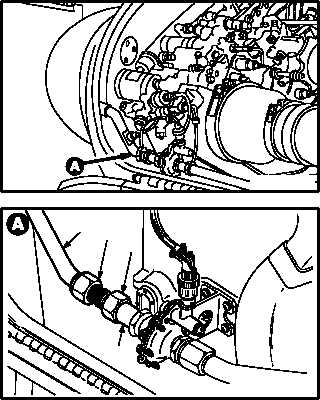
4.70.3. Removal
a. Remove engine anti-ice tube (1) from valve
(2).
(1) Hold union (3). Use open end wrench.
(2) Remove nut (4). Use crowfoot.
GO TO NEXT PAGE
M04-2583-1
3
M04-2583-2
2
4
1