TM 1-1520-238-23
Change 2
4-251
4.78.
NO. 2 ENGINE AIR DUCT REMOVAL/INSTALLATION – continued
4.78.6. Installation
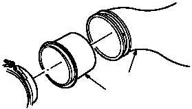
a. Install adapter (8) in duct (3).
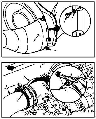
b. Install duct (3) on primary nozzle (5).
(1) Aline pin (9) at bottom of duct (3) with primary
nozzle (5).
(2) Install three bolts (6) through washers (7) and
duct (3) into nozzle (5).
NOTE
When installing coupling assembly, tight-
en coupling nut to approximately 70 per-
cent of maximum indicated torque. Tap
around outside of coupling with a rubber
mallet to distribute band tension. Torque
nut to specified value. Do not over torque.
c. Install duct (3) on particle separator blower
(4).
(1) Slide adapter (8) forward until flange (10)
alines with flange (11) of blower (4).
(2) Install coupling (1) around flanges (10) and
(11) with bolt (12) at top and facing inboard.
(3) Install coupling nut (2) on bolt (12).
d. Torque coupling nut (2) to 25 INCH-POUNDS.
Use torque wrench and mallet.
e. Inspect (QA).
f. Install No. 2 engine shroud (para 4.103).
g. Perform power plants maintenance operation-
al check (engine 2) (TM 1-1520-238-T).
h. Secure access door RN1 (para 2.2).
END OF TASK
M04-1071-10
8
3
M04-1071-11
5
6
7
3
9
M04-1071-9A
2
12
3
11
10
4
1