TM 1-1520-238-23
4-369
4.114.
NO. 1 AND NO. 2 ENGINE SWIRL FRAME DRAIN TUBE REMOVAL/INSTALLATION
(T700-GE-701C ENGINE) – continued
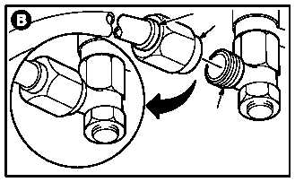
b. Remove tube (1) from swirl frame connector
(5).
(1) Hold connector (5). Remove nut (6).
4.114.4. Cleaning
a. Clean adapter and connector (para 1.47).
4.114.5. Inspection
a. Check adapter for damaged threads or loose-
ness. None allowed.
b. Check connector for damaged threads. None
allowed.
c. Check adapter and connector for corrosion
(para 1.49).
4.114.6. Installation
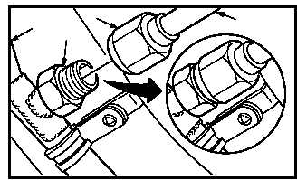
a. Install tube (1) on connector (5).
(1) Hand tighten nut (6) on connector (5).
b. Install tube (1) on manifold (2).
(1) Hand tighten nut (4) on adapter (3).
c. Torque nut (6) to 120 INCH-POUNDS.
(1) Hold connector (5). Torque nut (6) to 120
INCH-POUNDS. Use torque wrench.
d. Torque nut (4) to 120 INCH-POUNDS.
(1) Hold adapter (3). Torque nut (4) to 120 INCH-
POUNDS. Use torque wrench.
e. Inspect (QA).
f. Secure access doors LN2, LN3, and LN4 or
RN2, RN3, and RN4 (para 2.2).
END OF TASK
M04-3701-3
5
6
1
4
2
3
M04-3701-4
1