TM 1-1520-238-23
5-20
Change 3
5.3.
MAIN ROTOR BLADE REMOVAL – continued
5.3.3. Removal
NOTE
If blade is to be replaced, remove bal-
ance weights from blade root and
install on replacement blade.
If TB 1-1520-238-20-62 (Deactivation
of Main Rotor and Tail Rotor Blade De-
ice Capability) is complied with, then
step a. should have been complied
with. If not, perform step a.
a. On the pilot aft circuit breaker panel, disable
de-ice system by opening BLADE DE-ICE and
BLADE DE-ICE CONTR circuit breakers. Install
wire tie to prevent reactivation.
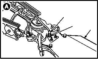
b. Position main rotor blade (1) to be removed
over forward fuselage.
c. Lock rotor brake (para 1.62).
d. Remove lockwire from power distributor con-
nector P1, P2, P3, or P4 (2).
e. Detach connector P1, P2, P3, or P4 (2) from
heater element receptacle J1 (3) on blade (1).
f. Record blade serial number and connector
number if removing blade for other mainte-
nance.
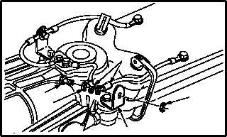
g. Remove two electrical leads (4) from angle
bracket (5).
(1) Hold bolt (6) and remove nut (7).
(2) Remove bolt (6), washer (8), and leads (4).
(3) Temporarily install bolt (6), washer (8), and
nut (7) for storage.
GO TO NEXT PAGE
M04-205-2
2
3
1
M04-205-3
6
8
4
5
7