TM 1-1520-238-23
5-58
Change 3
5.10.
MAIN ROTOR BLADE DROOP ANGLE MEASUREMENT – continued
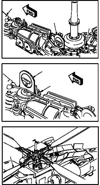
k. Set protractor (27) reference zero point.
(1) Place protractor (27) on main rotor driveplate
(28). Use protractor assembly.
(2) Aline body of protractor (27) with blade (8).
(3) Adjust protractor (27) for zero. This setting is
to be used as reference point.
l. Place protractor (27) on upper surface of out-
board pitch housing (29).
(1) Aline protractor (27) with blade (8). Use
protractor assembly.
m. Adjust protractor (27) inner dial to center level
bubble.
NOTE
This is droop angle reading and should
be 7 to 7-1/2 degrees from reference
zero point in step k.
One 0.020 INCH thick shim changes
droop above 1/2 degree.
Maximum number of shims is 9.
n. If needed, adjust droop angle to 7 to 7-1/2
degrees.
(1) If droop angle is too great, add shims (para
5.30).
(2) If droop angle is not enough, remove shims
(para 5.30).
GO TO NEXT PAGE
8
27
28
M04-209-2
27
29
M04-209-4
8
M04-209-10