TM 1-1520-238-23
5-74
Change 4
5.13.
MAIN ROTOR BLADE LEADING EDGE TIP REPLACEMENT – continued
(5) Allow adhesive to cure at room temperature
for 24 HOURS minimum.
c. Inspect (QA).
5.13.7. Installation
CAUTION
There are two different size screws
installed on the edge tip. If installed in the
wrong location they may damage the nut-
plate.
NOTE
Mismatch between edge tip and blade
over the first 2 INCHES of chordwise dis-
tance from leading edge shall not exceed
0.020 INCH. Mismatch on upper surface
should be minimized to make upper sur-
face as flush as possible.
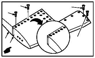
a. Install edge tip (1) on blade (2). Torque screws
(3) and screws (4) to 45 INCH-POUNDS.
(1) Install edge tip on blade (2) and aline screw
holes.
(2) Trim and file new tip cap, if required, to match
main rotor blade.
(3) Spot prime and paint exposed surfaces. Take
care to keep paint out of screw threads
(TM 55-1500-345-23).
(4) Coat 21 screws (3) and 3 screws (4) with
antiseize
compound.
Use
antiseize
compound (item 26, App F).
(5) Install 21 screws (3) and 3 screws (4), wet, on
edge tip (1) upper surface. Use hi-torque
screwdriver.
GO TO NEXT PAGE
M04-207-3A
4
4
4
2
1
3