TM 1-1520-238-23
5-112
Change 6
5.23.
MAIN ROTOR DAMPER REMOVAL/INSTALLATION – continued
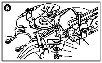
5.23.3. Removal
a. Remove main rotor damper rod end (1) from
lead lag link (2).
(1) Remove sealing compound from attaching
hardware. Use spatula set.
(2) Hold bolt (3). Use box wrench.
(3) Remove nut (4) and washer (5). Use ratchet.
(4) Remove bolt (3), angle bracket (6), and
sleeve bushing (7).
(5) Swing rod end (1) free from link (2) and re-
move washer (8).
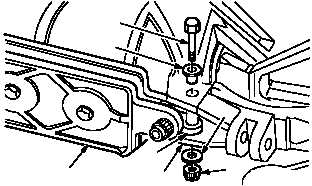
b. Remove damper trunnion (9) from pitch hous-
ing (10).
(1) Remove sealing compound from attaching
hardware. Use spatula set.
(2) Hold bolt (11). Use box wrench.
(3) Remove nut (12) and washer (13). Use
ratchet.
(4) Remove bolt (11) and sleeve bushing (14).
(5) Remove main rotor damper (15).
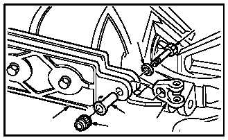
c. Remove trunnion (9) from damper (15).
(1) Remove sealing compound from attaching
hardware. Use spatula set.
(2) Hold bolt (16). Use box wrench.
(3) Remove nut (17) and bushing (18). Use
ratchet.
(4) Remove bolt (16) and washer (19) from
damper (15) and trunnion (9).
GO TO NEXT PAGE
M04-220-2
2
4
5
1
6
7
3
8
M04-220-6
11
14
15
9
10
12
13
16
19
9
18
17
15
M04-220-8