TM 1-1520-238-23
6-16
Change 4
6.2.
ENGINE INPUT DRIVE SHAFT AND OUTER DIFFUSER (ONE-PIECE)
REMOVAL/INSTALLATION – continued
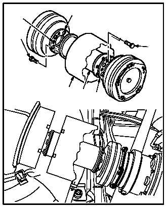
6.2.6. Installation
CAUTION
When installing drive shaft to coupling
flanges, ensure that bolts are installed
through 0.250 INCH coupling flange
holes and not through 0.500 INCH holes.
Installation of bolts through lightening
holes will result in failure of drive shaft
and/or couplings.
a. Install drive shaft (5) on flanges (6) and (7).
Torque bolts (8) and (9) to 125 INCH-POUNDS.
(1) Slide drive shaft (5) in diffuser (1).
(2) Position drive shaft (5) with diffuser (1) be-
tween flanges (6) and (7).
(3) Aline mounting holes.
(4) Install five bolts (9) through flange (7) and
shaft (5).
(5) Install five bolts (8) through flange (6) and
shaft (5).
(6) Torque bolts (8) and (9) to 125 INCH-
POUNDS. Use torque wrench adapter and
torque wrench.
(7) Apply corrosion preventive compound to
bolts (8) and (9). Use corrosion preventive
compound (item 62A, App F).
b. Inspect (QA).
GO TO NEXT PAGE
M04-0429-4
6
8
9
7
5
BOLT
HOLES
1