TM 1-1520-238-23
Change 4
6-55
6.10.
AFT HANGER BEARING AND SUPPORT REMOVAL/INSTALLATION – continued
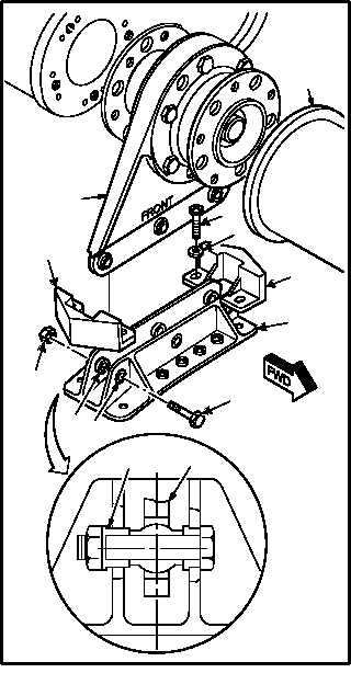
6.10.6. Installation
a. Install support (4) in bracket (5). Torque three
nuts (10) to 60 INCH-POUNDS. Torque four screws
(6) to 25 INCH-POUNDS.
NOTE
Epoxy primer must be applied to and
within 20 minutes of installation.
(1) Apply epoxy primer to mating surfaces of
support (4) and bracket (5). Use epoxy primer
coating kit (item 78, App F).
(2) Position support (4) in bracket (5) with word
FRONT facing forward. Aline bolt holes.
NOTE
Install bolts with bolt heads facing for-
ward.
Ensure that aft bushing does not bot-
tom out against the backside of brack-
et. Maintain clearance between
bushing flange and bracket.
(3) Install three bolts (9) through bushings (12),
bracket (5), support (4), and bushings (11).
(4) Install three nuts (10) on bolts (9).
(5) Torque three nuts (10) to 60 INCH-POUNDS.
Use torque wrench.
(6) Position two deflectors (8) on bracket (5).
Aline bolt holes.
(7) Install four screws (6) and washers (7)
through deflectors (8) and bracket (5).
(8) Torque four screws (6) to 25 INCH-POUNDS.
Use torque wrench, screwdriver bit holder,
and screwdriver bit.
(9) Apply corrosion preventive compound to four
screws (6), three bolts (9), and three nuts
(10). Use corrosion preventive compound
(item 62A, App F).
GO TO NEXT PAGE
M04-0445-3B
8
5
6
7
10
9
8
4
11
NO. 4
TAIL
ROTOR
DRIVE
SHAFT
12
CLEARANCE
SUPPORT