TM 1-1520-238-23
7-504
7.131.
SURGE VALVE EXHAUST INTERCONNECT TUBE REMOVAL/INSTALLATION – continued
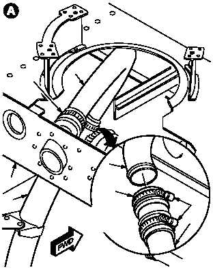
7.131.3. Removal
a. Remove tube (1) from exhaust duct (2) and
upper fuselage fairing frame (3).
(1) Loosen two clamps (4). Slide sleeve (5) on
duct (2).
(2) Loosen clamp (6). Remove tube (1).
7.131.4. Cleaning
a. Wipe removed and attaching parts with a
clean rag.
7.131.5. Inspection
a. Check duct, clamps, sleeves, and upper fuse-
lage fairing frame for cracks, dents, and tears
(para 7.114).
b. Check removed and attaching parts for corro-
sion (para 1.49).
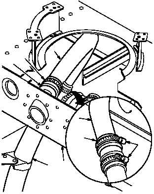
7.131.6. Installation
a. Install tube (1) between duct (2) and frame (3).
(1) Insert tube (1) into sleeve (7).
(2) Aline tube (1) with duct (2).
(3) Center sleeve (5) with clamps (4) on tube (1).
(4) Tighten two clamps (4) and one clamp (6).
b. Inspect (QA).
c. Perform pressurized air system leak check
(para 7.115).
d. Secure access doors T250L, T250R, T290L,
T290R, and L325; install fairing T225 (para
2.2).
END OF TASK
1
6
3
2
M04-2313-2
1
5
4
2
ROTATED
VIEW LOOKING
UP
1
6
3
2
1
5
4
7
M04-2313-3