TM 1-1520-238-23
6-112
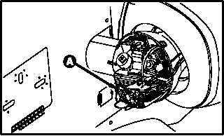
6.21.
ENGINE NOSE GEARBOX LOW OIL PRESSURE SWITCH REMOVAL/INSTALLATION
6.21.1. Description
This task covers:
Removal. Cleaning. Inspection. Installation.
6.21.2. Initial Setup
Tools:
Electrical tool kit (item 378, App H)
3/8 x 1/4-inch drive socket wrench adapter (item 7,
App H)
Light duty laboratory apron (item 27, App H)
3/4 x 3/8-inch drive open end socket wrench crowfoot
attachment (item 97, App H)
Industrial faceshield (item 129, App H)
Chemical protective gloves (item 154, App H)
10 - 50 inch-pound 1/4-inch drive click type torque
wrench (item 434, App H)
Materials/Parts:
Packing
Petrolatum (item 138, App F)
Wire (item 226, App F)
Personnel Required:
68X
Armament/Electrical System Repairer
67R3F
Attack Helicopter Repairer/Technical
Inspector
References:
TM 1-1520-238-T
TM 55-1500-323-24
Equipment Conditions:
Ref
Condition
1.57
Helicopter safed
2.123
Engine nose gearbox fairings and shrouds
removed
NOTE
This task is typical for either No. 1 or No.
2 engine nose gearbox low oil pressure
switch.
6.21.3. Removal
a. Enter pilot station (para 1.56). Observe all
safety precautions.
b. On pilot center circuit breaker panel, open LT
CAUT circuit breaker.
c. Enter CPG station (para 1.56). Observe all
safety precautions.
d. On CPG left console circuit breaker panel No.
1, open EMER BATT CAUT circuit breaker.
GO TO NEXT PAGE
M04-535-1