TM 1-1520-238-23
6-178
Change 8
6.36.
ENGINE NOSE GEARBOX AND QUILL SHAFT REMOVAL/INSTALLATION – continued
NOTE
If MWO 1-1520-238-50-47 has been
completed, go to step h.(1).
If MWO 1-1520-238-50-47 has not
been completed, go to step h.(2).
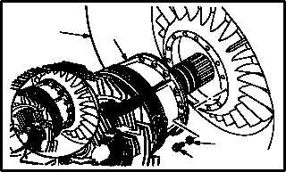
h. Install 15 bolts (20) and washers (21). Torque
15 bolts (20) to 120 INCH-POUNDS.
(1) Apply solid film lubricant to bolts (20). Use
lubricant (item 114, App F). Allow to cure for
6 HOURS at room temperature.
(2) With two persons supporting gearbox (19),
third person install 15 bolts (20) and washers
(21) evenly until seated on flange of gearbox
(19).
(3) Torque 15 bolts (20) to 120 INCH-POUNDS.
Use torque wrench and crowfoot.
NOTE
Pin wires for nose gearbox low oil pres-
sure switch to S25 splices (No. 1 nose
gearbox) or S26 splices (No. 2 nose
gearbox).
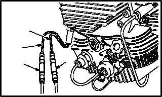
i. Pin identified wires (15) and (16) in splices
S25/S26 SP1 (17) and S25/S26 SP2 (18).
(1) Pin red wire (15) in splice S25/S26 SP1 (17)
(TM 55-1500-323-24).
(2) Pin white wire (16) in splice S25/S26 SP2
(18) (TM 55-1500-323-24).
NOTE
Pin wires for nose gearbox oil pressure
transducer to MT11 splices (No. 1 nose
gearbox) or MT12 splices (No. 2 nose
gearbox).
GO TO NEXT PAGE
M04-547-15
22
19
21
20
M04-547-16
15
17
18
16