TM 1-1520-238-23
6-296.14
Change 6
6.67A.
MAIN TRANSMISSION ROTOR BRAKE ACTUATOR (PARKER-HANNIFIN)
DISASSEMBLY/ASSEMBLY (AVIM) – continued
6.67A.7. Testing
CAUTION
Do not pressurize actuator on test bench
without first securing the actuator to the
test bench.
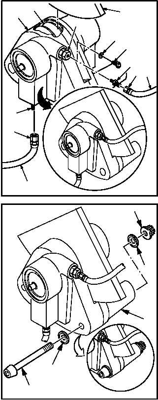
a. Install brake actuator (40) on test bench. Use
hydraulic test stand.
(1) Install pressure hose (41) to nipple (8).
(a) Lubricate threads of nipple (8). Use
hydraulic fluid (item 92, App F).
(b) Hold nipple (8). Install nut (42).
(2) Remove screw (12) and washer (13) from
bleed valve (10).
(3) Install bleeder hose (43) to bleed valve (10).
(a) Lubricate threads of tube reducer (44).
Use hydraulic fluid (item 92, App F).
(b) Hold valve (10). Install tube reducer (44).
(c) Hold tube reducer (44). Install nut (45).
(4) Insert brake disk test segment (46) (Figure
D-473, App D) between friction lining (30).
(5) Install two NAS 149-68 bolts (47), four
MS20002C9 washers (48), and two HS
4143-7 nuts (49) to hold brake actuator (40)
together while testing.
b. Perform static leak/brake return pressure test.
(1) Increase test bench hydraulic pressure to 300
PSI maximum and open bleed valve. Bleed
actuator until fluid flow displays no air is pres-
ent in bleeder outlet fluid. No flow is reason
for rejection.
(2) Decrease test bench hydraulic pressure to 0
PSI. Close and torque bleed valve to 40
INCH-POUNDS. Use torque wrench.
GO TO NEXT PAGE
M04-3771-21A
8
40
41
42
12
13
10
44
43
46
45
30
M04-3771-26
47
40
48
48
49