TM 1-1520-238-23
6-304.2
Change 6
6.68.
MAIN TRANSMISSION ROTOR BRAKE ACTUATOR (GOODYEAR/ABSC)
DISASSEMBLY/ASSEMBLY (AVIM) – continued
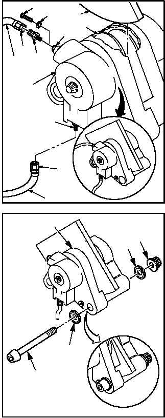
b. Install brake housing (1) on test bench. Use
hydraulic test stand.
(1) Install pressure hose (31) to nipple (29).
(a) Lubricate threads of nipple (29). Use
hydraulic fluid (item 92, App F).
(b) Hold nipple (29). Install nut (32).
(2) Remove screw (7) and washer (8) from bleed
valve (6).
(3) Install bleeder hose (33) to bleed valve (6).
(a) Lubricate threads of tube reducer (34).
Use hydraulic fluid (item 92, App F) and
tube reducer.
(b) Hold valve (6). Install tube reducer (34).
(c) Hold tube reducer (34). Install nut (35).
(4) Insert brake disk test segment (36) (Figure
D-473, App D) between friction lining (16).
(5) Install two NAS 149-68 bolts (37), four
MS20002C9 washers (38), and two HS
4143-7 nuts (39) to hold brake actuator hous-
ing (1) together while testing.
GO TO NEXT PAGE
M04-3337-13
29
32
31
33
35
34
7
8
6
36
1
16
M04-3337-18
1
37
38
39
38


