TM 1-1520-238-23
6-430
Change 1
6.97.
MAIN ROTOR SUPPORT MAST REMOVAL/INSTALLATION – continued
(c) Surface C.
1 apply corrosion preventative com-
pound to repaired area. Use
corrosion preventive compound
(item 63, App F).
2 Wipe off excess compound with a
clean rag. Use cloth (item 51, App F).
3 Apply corrosion preventative com-
pound to touched up area. Use
corrosion preventive compound
(item 62, App F).
b. Surface H.
(1) Missing plating on surface H, abrade with
abrasive cloth and apply primer, not to ex-
ceed 20 PERCENT of flange surface area.
Use cloth (item 48, App F) and epoxy primer
coating kit (item 78, App F).
c. Surface G.
(1) Check threads in surface G. Damage is al-
lowed to top 0.160 INCH starter threads.
(2) Check that damage does not exceed 0.003
INCH or penetrate through to base material.
Ensure retention nut is not impeded during
run–on.
(3) Check that lower edge of major diameter of
thread is within the 0.160 INCH on surface G.
(4) Blend damaged surface to a minimum of 20:1
ratio. Each contiguous blended area shall not
exceed a 2.0 INCH diameter.
GO TO NEXT PAGE
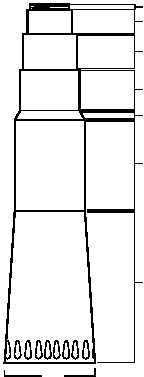
M04-520-9A
F
E
D
C
B
A
H
G