TM 1-1520-238-23
Change 4
6-435
6.98.
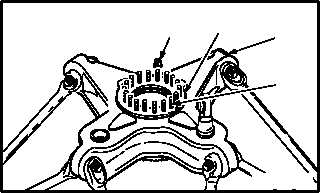
MAIN ROTOR MAST SUPPORT BASE SPACER PLATE REMOVAL/INSTALLATION – continued
6.98.6. Installation
CAUTION
Mating surfaces of spacer plate and sup-
port base must be prepared prior to
installation to ensure an acceptable elec-
trical bond. Mating surfaces must be free
of adhesive and chemical film treat-
ments.
a. Prepare spacer plate (1) and support base (2).
(1) Clean mating surfaces of spacer plate (1) and
support base (2) (para 1.47). Use methyl
ethyl ketone (item 124, App F).
(2) Apply coating to spacer plate (1) and support
base (2). Use corrosion resistant coating
(item 66, App F).
(3) Allow coating to stand on surfaces for 1.5 to 2
MINUTES, then remove excess coating with
a clean lint free cloth and water. Use cloth
(item 52, App F).
(4) Dry prepared surfaces with a clean lint free
cloth. Use cloth (item 52, App F).
b. Position spacer plate (1) over bolts (3) on sup-
port base (2) (TM 55-1500-323-24).
(1) Secure spacer plate (1) temporarily using
four nuts (4) spaced evenly around perimeter
of spacer plate (1).
c. Perform electrical bond check between
spacer plate (1) and support base (2)
(TM 55-1500-323-24).
(1) Bond shall be 0.005 OHM or less. Use
ohmmeter.
GO TO NEXT PAGE
1
2
M04-3540-2
4
3