TM 1-1520-238-23
6-569
6.138.
TAIL ROTOR GEARBOX TEMPERATURE SENSOR REMOVAL/INSTALLATION
6.138.1. Description
This task covers:
Removal. Cleaning. Inspection. Installation.
6.138.2. Initial Setup
Tools:
Aircraft maintenance tool kit (item 372, App H)
Light duty laboratory apron (item 27, App H)
5/8 x 3/8-inch drive open end socket wrench crowfoot
attachment (item 98, App H)
Industrial faceshield (item 129, App H)
Chemical protective gloves (item 154, App H)
10 - 50 inch-pound 1/4-inch drive click type torque
wrench (item 434, App H)
Materials/Parts:
Packing
Packing with retainer
Assembly fluid (item 30, App F)
Personnel Required:
68D
Aircraft Powertrain Repairer/NDI
67R3F
Attack Helicopter Repairer/Technical
Inspector
References:
TM 1-1520-238-T
TM 55-1500-323-24
Equipment Conditions:
Ref
Condition
1.57
Helicopter safed
2.2
Access fairings L530 and L540 removed
WARNING
FLIGHT SAFETY PART
The tail rotor gearbox is a flight safety
part. Failure to follow maintenance
instructions may result in serious
injury or death of crewmembers
and/or serious damage to the
helicopter.
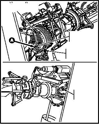
NOTE
This task is typical for all four tail rotor
gearbox temperature sensors.
Identify each sensor and each boss if
more than one sensor is removed at a
time.
GO TO NEXT PAGE
M04-562-4
LEFT SIDE
TEMPERATURE
SENSOR
FORWARD
TEMPERATURE
SENSOR
UPPER RIGHT
TEMPERATURE SENSOR
LOWER RIGHT
TEMPERATURE
SENSOR