TM 1-1520-238-23
8-24
8.8.
PILOT FUEL QUANTITY INDICATOR REMOVAL/INSTALLATION – continued
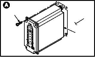
d. Remove fuel quantity indicator (1) from instru-
ment panel (2).
(1) Remove four screws (3).
(2) Pull indicator (1) from panel (2).
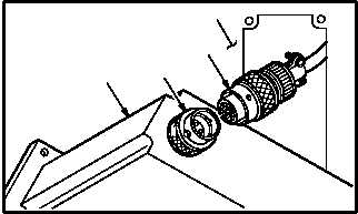
(3) Detach connector P253 (4) from receptacle
(M17)J1 (5).
8.8.4. Cleaning
a. Wipe mounting area and indicator with a clean
rag.
8.8.5. Inspection
a. Check indicator and panel mounting area for
cracks (para 8.1).
b. Check indicator and panel mounting area for
nicks and dents (para 8.1).
c. Check panel screw holes for stripped or dam-
aged threads (para 8.1).
8.8.6. Installation
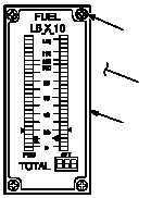
a. Install indicator (1) in panel (2).
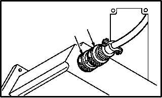
(1) Attach connector P253 (4) to receptacle
(M17)J1 (5).
(2) Aline indicator (1) with screw holes in panel
(2).
(3) Install four screws (3).
b. Inspect (QA).
c. Perform engine instruments maintenance op-
erational check (TM 1-1520-238-T).
END OF TASK
1
3
2
M04-155-3
2
4
M04-155-4
5
1
4
M04-155-5
5
M04-155-6
1
3
2