TM 1-1520-238-23
Change 7 9-475
9.127.
ROTOR BALANCE SIGNAL PROCESSOR UNIT REMOVAL/INSTALLATION – continued
9.127.6. Installation
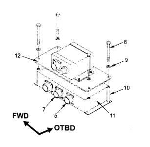
a. Install signal processor unit (11).
(1) Position signal processor (11) with connec-
tors (A141)J1 (5) and (A141)J2 (7) facing in-
board.
(2) Position filter box mounting plate (12) as
shown.
(3) Secure filter box mounting plate (12) and sig-
nal processor unit (11) to floor using four bolts
(8), washers (9), and spacers (10).
b. Perform electrical bond check between sig-
nal
processor
unit
(11)
and
floor.
(TM 1-1520-238-T).
(1) Bond shall be 0.0025 OHM or less. Use ohm-
meter.
c. Apply sealing compound around base of sig-
nal processor unit (5). Use sealing compound
(item 177, App F) and brush (item 34, App F).
d. Attach connector P128 (6) to receptacle
(A141)J2 (7).
e. Attach connector P129 (4) to receptacle
(A141)J1 (5).
f. Attach connector P128 (1) to receptacle J1 (2)
of filter box (3).
g. Inspect (QA).
h. Tilt and lock CPG seat in normal position (para
2.161).
i. Perform drive system vibration maintenance
operational check (TM 1-1520-238-T).
END OF TASK


