TM 1-1520-238-23
11-915
11.211.
PILOT DIRECTIONAL CONTROL POSITION LINEAR VARIABLE DIFFERENTIAL TRANSDUCER
(LVDT) INSTALLATION – continued
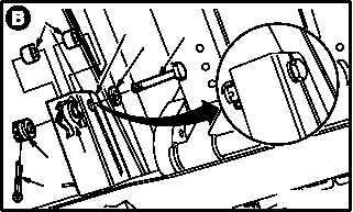
d. Install LVDT (2) on bracket (13). Torque nut (14)
14 to 18 INCH-POUNDS.
(1) Aline LVDT (2) with bracket (13).
(2) Install two bushings (15).
(3) Install bolt (16) through washer (17), bracket
(13), bushing (15), LVDT (2), bushing (15),
and other side of bracket (13).
(4) Check fit of self-retaining bolt (16) (para
11.1).
(5) Install nut (14). Torque nut (14) to 14 INCH-
POUNDS. Use torque wrench.
(6) Increase torque to aline cotter pin hole, but do
not exceed 18 INCH-POUNDS.
(7) Install new cotter pin (18).
e. Install pilot directional SPAD -9 rig pin (para
11.293).
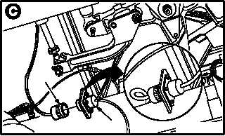
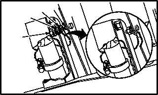
f. Attach connector P231 (8) to receptacle J231
(19).
g. Install lead (5) on ground stud (20).
(1) Position lead (5) on stud (20).
(2) Install washer (21) and nut (22).
h. Adjust LVDT null (para 11.216).
i. Remove pilot directional SPAD -9 rig pin (para
11.293).
j. Inspect (QA).
k. Perform directional flight control rigging
maintenance
operational
check
(TM 1-1520-238-T).
l. Install flex chute, turret, and area weapon
(TM 9-1090-208-23).
END OF TASK
M04-1860-3
16
17
14
2
13
18
15
M04-1860-5
8
19
M04-1860-8
20
5
21
22