TM 1-1520-238-23
11-1072
11.256.
DIRECTIONAL F.S. 275 PUSH-PULL ROD REMOVAL/INSTALLATION – continued
11.256.3. Removal
CAUTION
To prevent damage to flight control sys-
tem components, do not use force if bind-
ing or roughness occurs while moving
controls with hydraulic power.
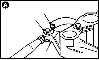
a. Install -9 rig pin (1) in directional F.S. 348 bell-
crank (2) and bracket (3).
(1) Locate bellcrank (2) and bracket (3).
(2) Install -9 rig pin (1) in bellcrank (2) and brack-
et (3). Use flight control rigging kit.
NOTE
If pin hole in bellcrank is not alined with
hole in bracket, slowly move controls to
aline holes.
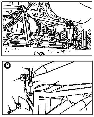
b. Install -5 rig pin (4) in directional F.S. 216.25
bellcrank (5) and bracket (6).
(1) Locate bellcrank (5) and bracket (6) on main
deck (7).
(2) Install -5 rig pin (4) in bellcrank (5) and brack-
et (6).
c. Remove external hydraulic power (para 1.72).
d. Remove directional control push-pull rod (8)
from forward bellcrank (5).
(1) Remove and discard cotter pin (9).
(2) Remove nut (10).
(3) Remove bolt (11).
(4) Remove bushing (12).
GO TO NEXT PAGE
M04-1800-4
1
2
3
M04-1800-5
5
6
4
7
9
10
12
5
8
11
M04-1800-2