TM 1-1520-238-T-4
4–8
4–2.
LOCATION AND DESCRIPTION OF MAJOR COMPONENTS (cont)
4–2
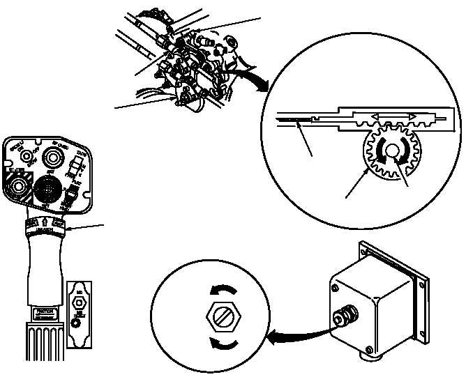
(d) Grip Control Collar.
A grip control (CHOP) collar switch is installed inside the chop collars on the
pilot and CPG collective sticks. The CHOP collar is spring–loaded in the aft position.
(e) Turbine Speed Control Unit.
The turbine speed control unit is located at the forward outboard
side of the aft avionics bay. This unit has a rpm adjustment screw, an electrical connector, and two internal
potentiometers (one for each engine).
M58-079
LOAD DEMAND SPINDLE (LDS)
(INPUTS FROM COLLECTIVE
SERVOCYLINDER OF
HYDRAULIC SYSTEM)
CONTROL CABLE
SPINDLE GEARBOX
RPM
ADJUSTMENT
INCREASE
DECREASE
HYDRO-MECHANICAL
UNIT (HMU)
GRIP CONTROL COLLAR
HMU SHAFT
TURBINE SPEED CONTROL
POWER AVAILABLE SPINDLE (PAS)
(INPUTS FROM PILOT AND
CPG POWER LEVERS)
COLLECTIVE STICK
Figure 4–7.
Engine Power Controls
(7) Engine Indicator Controllers.
The major components of the engine indicator controllers (fig. 4–8)
are the fuel pressure switch and the oil pressure transmitter.
(a) Fuel Pressure Switch.
Fuel pressure switch is an electro–mechanical device that monitors low
engine fuel pressure.
(b) Oil Pressure Transmitter.
The oil pressure transmitter is an electro–mechanical device.