TM 1-1520-238-T-4
4–25
4–7
SYSTEM DESCRIPTION (cont)
4–7
PILOT
POWER QUADRANT
START
LIGHT
M58-213
ENGINE
28 VDC
START
ENGINE START MODE
RELAY PANEL
SPEED
CONTROL
SWITCH
REGULATOR ENERGIZE
INTERLOCK VALVE
IGNITION
ENABLE
ELECTRICAL POWER
DISTRIBUTION BOX
SPEED SENSOR
ENCU
SHUTOFF VALVE
PRESSURIZED
AIR
PAS
PRESSURIZED
AIR
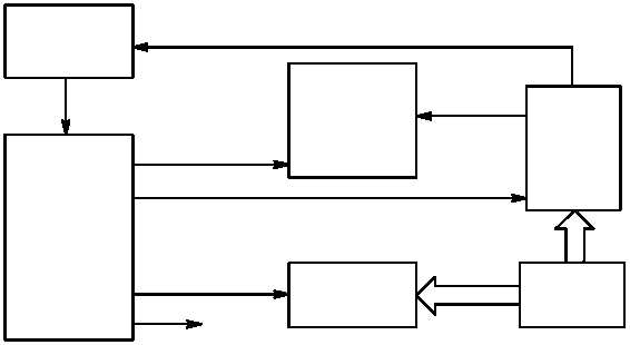
Figure 4–17.
Engine Start System Block Diagram
(5) Power Quadrants.
The power quadrants (fig. 4–6) provide command inputs to the HMU on each
engine. The HMU controls the amount of fuel supplied to the engines.
(a) The pilot and CPG power quadrants transmit power selections from the crew stations to the engines.
The engines are controlled by two power levers. The left lever operates engine 1. The right lever operates the
engine 2. The power levers must be placed in IDLE to return to automatic control which are then advanced to the
FLY position. The pilot power quadrant has mechanical stops to prevent the pilot and CPG power levers from
being moved from FLY to LOCKOUT or from IDLE to OFF. The CPG power quadrant does not have mechanical
stops. The stops are released by a trigger release on the power levers. The stop release levers on the CPG
power levers operate a solenoid. The solenoid frees the mechanical stops on the power quadrants. A friction
power lever on the pilot power quadrant applies friction to both power levers to hold the levers in place.
(6) Engine Power Controls.
The engine power controls provide inputs to the HMU on each engine. The
HMU controls the amount of fuel supplied to the engine. Inputs are provided by the pilot and CPG power quadrant
power levers, collective stick, and turbine speed control unit.
(a) The power levers (fig. 4–18) are connected by control cables to the power available spindle on the
respective engine HMU. Moving a power lever causes the control cable to move the respective power available
spindle on the HMU. Normally, the power levers are used to set the engine speed to OFF, IDLE or FLY when the
collective is at flat pitch.
(b) A CHOP collar is installed on the pilot and CPG collective sticks. The collar provides for rapid
reduction of engine power. Pushing forward and twisting clockwise reduces engine power to idle. Pushing forward
and twisting counter–clockwise causes both engines to return to the previous power setting. Pushing the
collective stick down reduces the fuel flow to the engine to compensate for a power demand decrease. When the
collective is moved, the LVDT develops a signal that is proportional to the rate and amount of movement. This
signal is applied to both engine ECUs or DECUs to help the engines maintain 100% NP/NR under high power
requirements. The collective stick actuator is connected by control cables to the load demand spindles on both
engines. Pulling the collective stick up causes the load demand spindle to move, supplying more fuel to the
engine to compensate for the increased power demand on the engines.