TM 1-1520-238-T-4
5–3
5–2
LOCATION AND DESCRIPTION OF MAJOR COMPONENTS (cont)
5–2
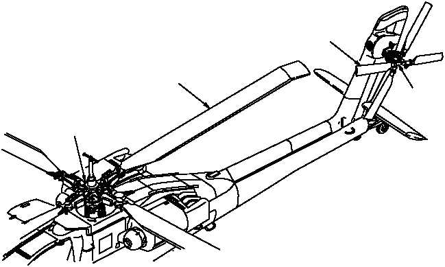
TAIL ROTOR BLADE (4)
TAIL ROTOR
HEAD
ASSEMBLY
M58-119B
MAIN ROTOR BLADE (4)
MAIN ROTOR
HEAD ASSEMBLY
Figure 5–1.
Rotor System
(1) The hub assembly is mounted on the main drive shaft static mast and provides attachment points for
the four main rotor blade assemblies. It provides the means for feathering, flapping, and lead–lag movement of
each blade. It transfers flight loads from the main rotor assembly to the static mast and into the airframe.
(2) Four strap packs are bolted to the hub. Each strap pack has V–shaped stainless steel straps. The
lead–lag links are attached to the strap packs and pitch housing assemblies.
(3) The pitch housing assembly uses a feathering bearing assembly between the hub and housing
assemblies. The feathering bearing allows the pitch housing assembly to move up and down. An arm on each
pitch housing assembly is attached to the cyclic controls through a pitch link. Control inputs twist the pitch housing
assembly to cause angle changes in main rotor blade assembly.
(4) The droop stop follower contacts the droop stop ring to limit the pitch housing downward movement
when the main rotor blade assembly is stopped.
(5) The blade attachment pins are made of steel and are an adjustable bushing type that allows for easy
removal or installation of the blades.
(6) Two dampers are attached between each pitch housing and its lead–lag link. The dampers are used to
control the lead–lag movement of the rotor blades and prevent mass imbalance (unequal blade spacing).
(7) The lead–lag links (4 ea) are titanium mounts that provide mounting points for the main rotor blade
assembly.