TM 1-1520-238-T-5
7–12
Change 1
7–3.
EQUIPMENT DATA
7–3
Not applicable.
7–4.
EQUIPMENT CONFIGURATION
7–4
Not applicable.
7–5.
SAFETY, CARE AND HANDLING OF EQUIPMENT
7–5
Not applicable.
7–6.
CONTROLS AND INDICATORS
7–6
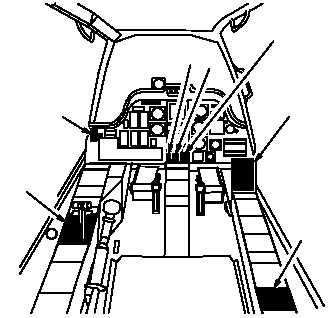
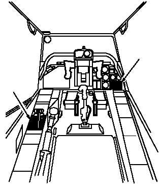
The hydraulic and pneumatic systems receive mode selects and remote switch inputs from various controls
located in the pilot station (fig. 7–4) and the CPG station (fig. 7–5). Table 7–1 provides a listing of the controls,
switches and associated indicators pertaining to the hydraulic and pneumatic systems along with a description of
their function.
M68-164A
5
6
1
2
3
4
7
1.
PILOT POWER QUADRANT
2.
PILOT TAIL WHEEL LOCK PANEL
3.
PILOT EMERGENCY HYDRAULIC (EMER HYD)
CONTROL PANEL
4.
PILOT EMERGENCY HYDRAULIC PRESSURE
INDICATOR
5.
PILOT DUAL HYDRAULIC PRESSURE INDICATOR
6.
PILOT CAUTION/WARNING PANEL
7.
PILOT APU PANEL
Figure 7–4.
Pilot Station
M68-165A
1
2
1.
CPG POWER QUADRANT
2.
CPG CAUTION/WARNING PANEL
Figure 7–5.
CPG Station


