TM 1-1520-238-T-5
7–89
7–21.
UTILITY HYDRAULIC SYSTEM – MAINTENANCE OPERATIONAL CHECK (cont)
7–21
Task
Result
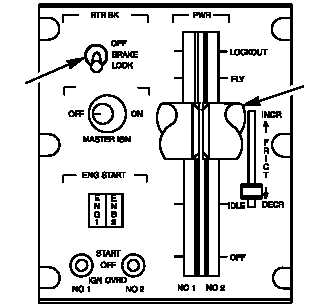
ap. Check that RTR BK switch located on pilot
power quadrant (fig. 7–48) is OFF. Hand
rotate main rotor blade assembly.
If main rotor blade assembly does not rotate (rotor
brake does not release), go to paragraph 7–34.
aq. On pilot caution/warning panel (fig. 7–36),
check RTR BK indicator is off.
If RTR BK indicator is on, go to paragraph 7–35.
M68-030A
RTR BK
SWITCH
PWR
LEVERS
Figure 7–48.
Pilot Power Quadrant
ar. To stop blade rotation, set RTR BK switch to
BRAKE.
If rotor brake does not stop rotation of rotor
assembly and RTR BRK circuit breaker is
closed, go to paragraph 7–36.
If rotor brake does not stop rotation of rotor
assembly and RTR BRK circuit breaker is open,
go to paragraph 7–33.
as. On pilot caution/warning panel (fig. 7–36),
check that RTR BK indicator is on.
If RTR BK indicator is off, go to paragraph 7–37.
at. Disconnect and remove AGPU hydraulic
pressure from helicopter
(TM 1-1520-238-23).
au. Start helicopter APU (TM 1-1520-238-23).
If APU start sequence does not begin, refer to
TM 1-1520-238-T-8 to troubleshoot APU.
av. On pilot instrument panel, check that UTIL
HYD indicator (fig. 7–38) indicates 3000
PSI.
If UTIL HYD indicator does not indicate 3000
PSI, go to paragraph 7–38.