TM 1-1520-238-T-6
9–31
9–2.
LOCATION AND DESCRIPTION OF MAJOR COMPONENTS (cont)
9–2
r. Circuit Protection System.
(1) Pilot station ac essential bus 1 circuit protection.
NOTE
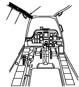
Refer to pilot station (fig. 9–19) for configuration and component locations.
M69-192
1.
PILOT AFT CIRCUIT BREAKER PANEL
2.
PILOT CENTER CIRCUIT BREAKER PANEL
3.
PILOT FORWARD CIRCUIT BREAKER PANEL
1
2
3
Figure 9–19.
Pilot Station
Table 9–13 contains a listing of the circuit breakers associated with the pilot station ac essential bus 1, along with
each circuit breaker’s rating in amps.
Table 9–13.
Pilot Station AC Essential Bus 1 Circuit Protectuion
Pilot Forward Circuit Breaker Panel (fig. 9–20)
CB NO.
CB NAME
RATING
CB41
MISSION IHADSS
5 amp
CB42
NAV HARS AC
5 amp
CB43
NAV HSI
5 amp
CB45
MISSION SYM GEN
5 amp
CB51
MISSION FC AC
5 amp
CB74
MISSION RDR JAM AC
5 amp