TM 1-1520-238-T-6
9–41
9–2.
LOCATION AND DESCRIPTION OF MAJOR COMPONENTS (cont)
9–2
(5) Pilot station dc essential bus 1 circuit protection.
NOTE
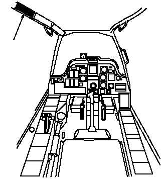
Refer to pilot station (fig. 9–30) for configuration and component locations.
M69–214
1.
PILOT AFT CIRCUIT BREAKER PANEL
1
Figure 9–30.
Pilot Station
Table 9–17 contains a listing of the circuit breakers associated with the pilot station dc essential bus 1, along with
each circuit breaker’s rating in amps.
Table 9–17.
Pilot Station DC Essential Bus 1 Circuit Protection
Pilot Aft Circuit Breaker Panel (fig. 9–31)
CB NO.
CB NAME
RATING
CB5
POWER BATT CHGR DC
20 amp
CB6
STAB MAN DC
15 amp
CB67
ECS ENG ANTI-ICE
5 amp
CB70
ECS CANOPY ANTI-ICE CONTR
5 amp
CB71
ECS WSHLD WPR
15 amp
CB94
CBR BLWR
5 amp

