TM 1-1520-238-T-7
10–52
10–7.
SYSTEM DESCRIPTION (cont)
10–7
DC BUS 2
FUEL TRANS
CB56
EXT TK
SWITCH
1
2
3
4
5
6
DC EMER BUS
EXT EMP
PILOT
CAUTION / WARNING
PANEL
CLOSE
OPEN
CLOSE
OPEN
OPEN
AUX TANK AIR
SHUTOFF VALVE
LEFT AUX TANK
FUEL
SHUTOFF VALVE
RIGHT AUX TANK
FUEL
SHUTOFF VALVE
LEFT INBD
AUX TANK
FUEL EMPTY
SWITCHES
RIGHT INBD
AUX TANK
M70-218
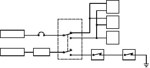
Figure 10–27.
Auxiliary Tanks Electrical Diagram
10–8.
MULTIPLEX READ CODES
10–8
Not applicable.
SECTION III.
TROUBLESHOOTING PROCEDURES
10–9.
ELECTRICAL COMPONENT LOCATION AND CONFIGURATION (ECLC) INDEX
10–9
Use the information in Table 10–2 to locate the electrical components and their connectors to perform the
troubleshooting tasks in this chapter. Table 10–2 includes locator illustrations which supplement the ECLC listing.
The listing entry in the grid area column tells where to locate the component in the illustrations.
Table 10–2.
Electrical Component Location and Configuration (ECLC) Index Listing
FROM COLUMN
TO COLUMN
Connector
Ref Des
Component/
Harness
Connector
Ref Des
Component/
Harness
Grid
Area
Access
P1
A322
J1039
W119
7A
CPG STATION
P1
W605/A76
J1
A402
32B
R200 PANEL
P1066
W118
J1
S65
44C
PLT STATION
P1067
W268
J1
S64
70E
L325 DOOR
P1085
W118
J1
A146
62D
B200 DOOR


