TM 1-1520-238-T-7
11–27
11–2.
LOCATION AND DESCRIPTION OF MAJOR COMPONENTS (cont)
11–2
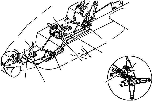
ASSEMBLY
SWITCH
SHEAR PIN
M70-337
TYPICAL SPAD
CPG LONGITUDINAL SPAD
PILOT LONGITUDINAL SPAD
CPG LATERAL SPAD
CPG DIRECTIONAL
SPAD
PILOT COLLECTIVE SPAD
PILOT DIRECTIONAL
SPAD
CPG COLLECTIVE
SPAD
PILOT LATERAL SPAD
Figure 11–10.
SPAD Locations
g. SCS.
The SCS (fig. 11–11) consists of the stabilator, two pitch rate gyros, two airspeed transducers, the
stabilator cylinder assembly, SCUs, stabilator position transducer, STAB POS indicators, and the stabilator relay
box.
(1) Stabilator.
The stabilator, located at the base of the vertical stabilizer and mounted to the tail boom,
is a wing shaped airfoil and is automatically controlled by two independent electrical control systems: automatic
mode (DASE) and manual mode. The SCUs position the stabilator automatically at or above 30 knots forward
airspeed.
(2) Pitch Rate Gyros.
Pitch rate gyro 1 is mounted in the left side of the aft equipment bay. Pitch rate
gyro 2 is mounted in the right side of the aft equipment bay. They provide pitch rate signals to the SCUs. The pitch
rate gyros are sealed LRUs which are mounted in the pitch axis of the helicopter. When the helicopter deviates
from straight and level flight, the gyros develop a signal proportional to the rate and direction of deviation.
(3) Airspeed Transducers.
Airspeed transducer 1 is mounted in the left side of the aft equipment bay.
Airspeed transducer 2 is mounted in the right side of the aft equipment bay. They are sealed LRUs that develop
an electrical signal which is proportional to airspeed.