TM 1-1520-238-23
11-1075
11.256.
DIRECTIONAL F.S. 275 PUSH-PULL ROD REMOVAL/INSTALLATION – continued
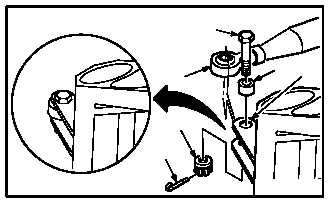
b. Install nonadjustable end of directional F.S.
275 push-pull rod (8) on forward bellcrank (5).
Torque nut (10) 30 to 40 INCH-POUNDS.
(1) Aline rod (8) with bellcrank (5).
(2) Install bushing (12).
(3) Install bolt (11) through bushing (12), bell-
crank (5), and rod (8).
(4) Check fit of self-retaining bolt (11) (para 11.1).
(5) Install nut (10). Torque nut (10) to 30 INCH-
POUNDS. Use torque wrench.
(6) Increase torque to aline cotter pin hole, but do
not exceed 40 INCH-POUNDS.
(7) Install new cotter pin (9).
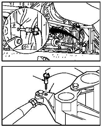
c. Remove -5 rig pin (4) from bellcrank (5).
d. Remove -9 rig pin (1) from bellcrank (3).
e. Inspect (QA).
f. Perform directional flight control rigging op-
erational check (TM 1-1520-238-T).
g. Secure access doors T250L, T250R, T290L,
T290R, and L325; install fairing T355 (para
2.2).
END OF TASK
M04-1800-6
9
10
12
5
8
11
4
5
M04-1800-9
M04-1800-8
1
3