
TB 1-1520-238-30-14
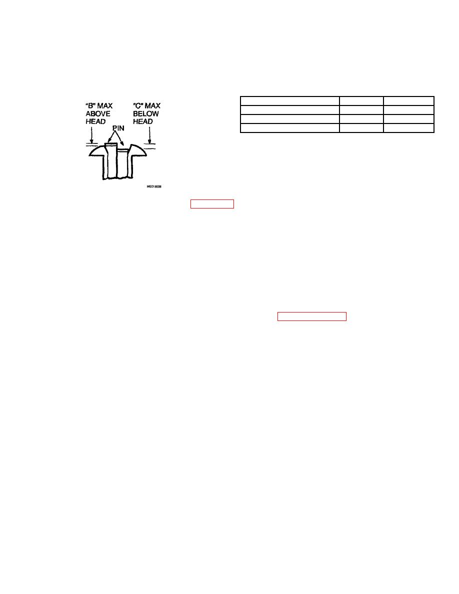
(6) Inspect the installed rivet lAW the installation below. Remove any rivets exceeding this inspection criteria
IAW TM 1-1500-204-23.
Rivet
B Max
C Max
NAS1398-CW5A(*)
.020
.010
NAS1398-CW6A(*)
.020
.010
CR6253-5-(*)
.010
.020
(7)
Replace any removed rivets IAW paragraph 9.c. of this TB.
(8)
Touch-up rivets and exposed surfaces with primer (MIL-P-23377) and paint (MIL-C-46168), lAW
TM 55-1500-345-23.
10. Visu-Lok\Jo-Bolt Installation Procedure.
a. This procedure is only to be used in conjunction with the Visu-Lok fastener, PLT251-5.
CAUTION
Visu-Lok blind fasteners are made from hard tool steel. Visu-Loks require the use
of special tools for installation and removal (reference paragraph no. 12). Failure
to use this tooling, or its improper use, may result in damage to airframe.
NOTE
In this application, the Visu-Lok fastener are to be installed into interference fit
holes. The fastener shall not be turned during the installation.
b. PLT251-5 fastener require a hole dimension of .1775/.1755 (interference fit).
NOTE
Install the fastener(s) while the primer is in a wet condition. Avoid contaminating
the driving head of the fastener with primer, prior to driving the fastener c. Insert
the fastener, wet with primer (MIL-P-23377) into the prepared hole. Ensure the full
seating of the head before driving the fastener. The fastener may be installed into
the hole by one of the methods listed below. Avoid damage to the drive screw or
core bolt during seating of the fastener head.
(1) Tapping the head with a nonmetallic-faced tool.
(2) Tapping the head with a nonmetallic block placed between the tool and the fastener head.
(3) Driving the fastener with a light rivet gun using a flush-type rivet to seat the fastener.
d. Setup the specified Visu-Lok installation tooling (non-powered or powered). Insert the nose adapter to engage
the fastener body with the wrench adapter engaging the slabbed portion of the driving screw.
4
