TM 1-1520-238-10
3-30
Change 6
Section III.
NAVIGATION
3.11 INTRODUCTION.
The navigation systems of the AH–64 are divided into 3
major groupings: Stand Alone Radio Navigational Aids; a
non–integrated navigation system; and a integrated navi-
gation system. The stand alone radio navigation aids con-
sist of the AN/ARN–89 or the AN/ARN 149(V)3 Automatic
Direction Finder (ADF) Sets. The non integrated naviga-
tion system consists of the AN/ASN–128 or AN/ASN–137
Doppler Navigation Sets (DNS), the IP–1552G Computer
Display Unit (CDU) and the Heading Attitude Reference
System (HARS). In aircraft equipped with the non–inte-
grated navigation system, the installed Doppler Naviga-
tion Set performs the navigation calculations. The inte-
grated navigation system consists of the Embedded
Global Positioning System (GPS) Inertial (EGI) unit, the
Air Data Sensor Subsystem (ADSS), the HARS, the AN/
ASN–137 DNS, the IP–1552G Computer Display Unit
(CDU) and the navigation software module in the Fire
Control Computer (FCC). In aircraft with the integrated
navigation system, all navigation calculations are per-
formed by the navigation software module in the FCC. A
Data Transfer Unit (DTU) is used in the integrated naviga-
tion system to provide bulk loading of navigational data.
NOTE
During an electrical system malfunction and
operating on EMERG BATT power, the HSI/
RMI will not provide adequate indications to
the station.
3.12 AUTOMATIC DIRECTION FINDER SET
AN/ARN–89
Direction finder set AN/ARN-89 is an airborne, Low Fre-
quency (LF), Automatic Direction Finder (ADF) radio that
provides an automatic or manual compass bearing on any
radio signal within the frequency range of 100 to 3,000
kHz. The ADF displays helicopter bearing relative to a se-
lected radio transmission. On the pilot instrument panel, it
is shown by the No. 2 bearing pointer of the Horizontal Sit-
uation Indicator (fig 2-9) On the CPG panel, it is shown on
the bearing pointer of the Radio Magnetic Indicator (RMI)
(fig 2-10). The ADF has three modes of operation that per-
mit it to function as a Continuous Wave (CW) Automatic
Direction Finder, a (CW) Manual Direction Finder, or as an
Amplitude-Modulated (AM) broadcast receiver. Power to
operate the set is provided through the ADF circuit break-
er on the pilot overhead circuit breaker panel.
3.12.1 Antennas. The ADF antennas (fig 3-1) are lo-
cated on the bottom center fuselage area, aft of the Dop-
pler/Radar Altimeter antenna fairing. The ADF loop anten-
na is mounted under the aft fairing. The ADF sense wire
antenna is supported between the aft fairing and a 7-inch
standoff 12 feet aft of the fairing.
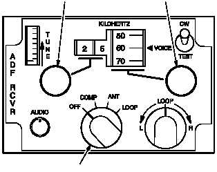
3.12.2 Controls and Function. Controls for the AN/
ARN-89 are on the front panel of the C-7392 (fig 3-8)
installed on the pilot right console. The function of each
control is described in table 3-9.
100 KILOHERTZ COARSE
TUNE CONTROL
10 KILOHERTZ FINE
TUNE CONTROL
MODE SELECTOR
M01-032
Figure 3-8.
Control Panel AN/ARN-89
Table 3-9.
AN/ARN-89 Control Functions
Control
Function
Mode selector
switch
OFF
Turns power to the set OFF.
COMP
Provides for operation as an ADF.