TM 1-1520-238-23
1-326.4
Change 8
1.108A. MAIN ROTOR TRACK AND BALANCE AVA KIT INSTALLATION – continued
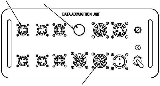
ACC 1
ACC 3
TACHO 1
ACC 2
ACC 4
TACHO 2
MULTI-CH
TRACKER 1
28 VDC
POWER
ON
OFF
TRACKER
MODE
CADU
STROBE
FUSE
15 AMP
NIGHT
DAY
TEST
12
13
14
M04-5208-6
(5) Attach UTD cable to DAU receptacle labeled TRACKER 1 (12).
NOTE
If signal processing unit is suspected defective, go to subparagraph 1.108A.6.
If night tracking is required, go to subparagraph 1.108A.7, otherwise go to to step (6).
(6) Ensure that TRACKER MODE switch on front of DAU is in DAY (13) position.
e. Inspect (QA).
f. Perform main rotor track and balance maintenance operational check (TM 1-1520-238-T).
1.108A.6. SPU Bypass Installation Instructions
NOTE
This step provides instructions for bypassing the signal processing unit (SPU). This is done if SPU is
defective.
a. Detach connector from lateral accelerometer located above and to the rear of pilots head.
b. Attach accelerometer cable (29105600) to the lateral accelerometer.
c. Route cable to CPG station and attach to receptacle marked ACC1 (14) on DAU.
GO TO NEXT PAGE