TM 1-1520-238-23
2-194
Change 3
2.61.
PILOT DOOR TRANSPARENT PANEL ASSEMBLY REMOVAL/INSTALLATION – continued
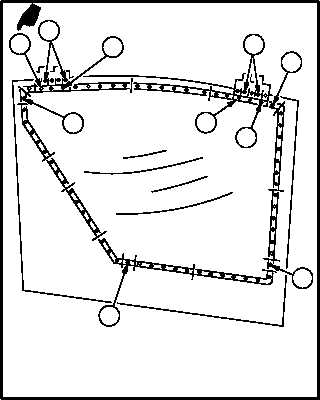
e. Tighten four screws (9) in sequence A, B, C,
and D as shown in illustration, until screws (9)
are snug against washers (10).
f. Tighten 55 screws (9) in group sequence
shown in illustration, until screws (9) are snug
against washers (10).
g. Torque four alinement screws (9) to 5 INCH-
POUNDS in sequence A, B, C, and D as shown
in illustration. Use torque wrench.
NOTE
Torque sequence groups 6 and 12 re-
quire different torques in each group.
h. Torque 55 screws (9) to 5 INCH-POUNDS.
Torque six screws (5) to 15 INCH-POUNDS in
group sequences shown in illustration. Use
torque wrench.
i. Torque eight screws (4) to 20 INCH-POUNDS.
Use torque wrench.
j. Seal around panel (7). Use sealing compound
(item 176, App F) and sealant gun.
k. Inspect (QA).
l. Install pilot station access door (para 2.62).
END OF TASK
M04-1454-8A
10
4
12
1
7
5
9
3
11
2
8
6
9
5
4
5
B
4
5
5
9
C
9
9
D
A
TORQUE SEQUENCE CHART


