TM 1-1520-238-23
Change 9
2-312.1
2.88.
ROTOR SUPPORT MAST SUPPORT BASE REMOVAL/INSTALLATION – continued
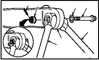
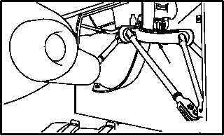
b. Install mast base (1) on struts (4) and (6).
(1) Lower mast base (1) on four struts (4) and
(6). Use sling.
(2) Aline struts (4) and (6) to base (1). Use
driftpin.
(3) Install four bolts (7) through washers (10) and
mast base (1).
(4) Install four nuts (9) on bolts (7) finger tight.
(5) Ensure four nuts (9) have no less than
50 INCH-POUNDS run-on torque. Use
torque wrench.
c. Torque four nuts (9) 280 to 304 FOOT-
POUNDS.
(1) Hold four bolts (7). Torque nuts (9) to 280
FOOT-POUNDS. Use torque wrench,
adapter, and 5-inch extension.
(2) If cotter pin hole is not alined, increase torque
to aline. Do not exceed 304 FOOT-POUNDS.
(3) Install new cotter pin (8) in alined hole.
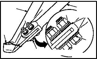
d. Torque four bolts (5) to 290 FOOT- POUNDS
and lockwire to strut (6). Use torque wrench
and socket wrench.
e. Torque eight nuts (2) to 600 INCH- POUNDS to
secure strut (4).
(1) Hold eight bolts (3). Torque nuts (2) to
600 INCH-POUNDS. Use torque wrench and
adapter.
f. Check for maximum gap of 0.050 INCH under
washer (13) at bolt head (3) and under washer
(14) at nut side (2). Use thickness gage. Replace
bolt if gap exceeds 0.050 INCH.
g. Remove sling from base (1).
h. Inspect (QA).
i. Install main rotor support mast (para 6.97).
j. Install main transmission (para 6.107).
k. Install longitudinal and collective bellcranks
(para 11.9).
END OF TASK
M04-3086-6A
7
9
10
TYPICAL
8
4
6
1
2
4
3
5
6
13
M04-3086-16B
14
VIEW ROTATED
0.050 INCH
MAX GAP
1
M04-3086-10


