TM 1-1520-238-23
Change 1
2-309
2.88.
ROTOR SUPPORT MAST SUPPORT BASE REMOVAL/INSTALLATION – continued
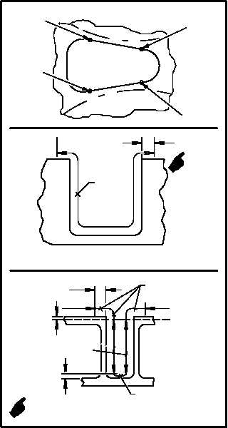
(9) Maximum allowable depth for triangular cav-
ity:
(a) Inboard curved walls (A-B) are 0.265
INCH (this measurement extends 0.500
INCH beyond top hole lip); outboard
curved walls (C-D) are 0.265 INCH (this
measurement extends 0.500 INCH be-
yond top lip of hole to top surface); 1.00
INCH from base of triangle to 3.10 INCH-
ES outboard (A-D) is 0.265 INCH (this
measurement extends 0.070 INCH
above bottom of hole); side walls (B-C)
are 0.125 INCH (this measurement ex-
tends to 0.230 INCH below the top lip of
hole). Use flashlight and mirror.
GO TO NEXT PAGE
M04-3086-14A
0.070
0.230
0.265*
0.125*
0.265*
A
B
D
C
0.265*
(A-D)
(B-C)
(A-D)
(B-C)
DENOTES MAXIMUM PITTING ALLOWED
*
0.500
(2 PLACES)