TM 1-1520-238-23
2-436
2.121.
WING INSTALLATION – continued
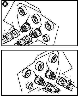
c. Install nonmetallic hose assembly (9) on cou-
pling assembly (10).
(1) Place rags under hose (9) and coupling (10)
to catch fluid spills.
(2) Install hose (9) on coupling (10).
(3) Turn sleeve (11) clockwise on hose (9) until
seated and locking teeth fully engaged.
d. Install hose assembly (12) on coupling half
(13).
(1) Install hose (12) on coupling (13).
(2) Turn sleeve (14) clockwise on hose (12) until
seated and locking teeth fully engage.
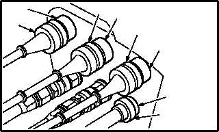
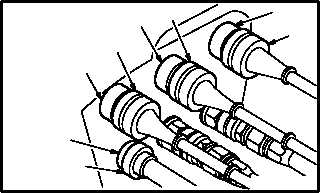
e. Attach four left wing connectors (15), (16),
(17), and (18) to receptacles (19), (20), (21),
and (22).
(1) Attach connector P115 (15) to receptacle
J115 (19).
(2) Attach connector P587 (16) to receptacle
J587 (20).
(3) Attach connector P1075 (17) to receptacle
J1075 (21).
(4) Attach connector P586 (18) to receptacle
J586 (22).
GO TO NEXT PAGE
M04-1523-13
11
14
12
13
10
9
LEFT SIDE
11
10
13
14
M04-1523-14
12
9
RIGHT SIDE
M04-1523-15
22
18
17
21
16
20
19
15
LEFT SIDE
18
M04-1523-16
21
16
20
19
15
22
17
RIGHT SIDE


